Description
Writes all setting data stored in "set". The data format depends on each setting data. The format of Byte/Word/2-Word setting data is generally signed binary.
Writes the setting data for all axes once by specifying 'ALL_AXES' in 'type'. The setting data for each axis must be stored in each array of "IODBPSD".
The attribute of setting data depends on the type and axis, and it is different for each setting data. It is as follows, and can be got by cnc_rdsetinfo function.
| Setting data type | Meaning | Byte size |
|---|---|---|
| Bit setting data | Every bits have each definition. | 1 |
| Bit setting data with axis | Every bits have each definition. (each axis) | 1 |
| Byte setting data | 1-byte data is stored. | 1 |
| Byte setting data with axis | 1-byte data is stored. (each axis) | 1 |
| Word setting data | 2-byte data is stored. | 2 |
| Word setting data with axis | 2-byte data is stored. (each axis) | 2 |
| 2-Word parameter | 4-byte data is stored. | 4 |
| 2-Word parameter with axis | 4-byte data is stored. (each axis) | 4 |
| Real setting data (Series 15i, 30i, 0i-D/F, PMi-A) |
4-byte data which indicates value of variable and 4-byte data which indicates number of places of decimals are stored. | 8 |
| Real setting data with axis (Series 15i, 30i, 0i-D/F, PMi-A) |
4-byte data which indicates value of variable and 4-byte data which indicates number of places of decimals are stored. (each axis) | 8 |
It is impossible to write any bit setting data bit by bit. 8 bits(i.e. 1 byte) which belong to the same setting data number are written at the same time.
This function is the same as cnc_wrparas function except that it cannot write the parameter without setting attribute.
See the "PARAMETER MANUAL" of CNC for details of each setting data.
Universal Fanuc Driver
Fanuc Focas Library CD
Declaration
Arguments
Specify the library handle. See "Library handle" for details.
Specify the data block length which is enough to store the specified setting data.
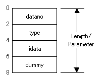
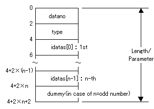
The structure per 1 setting data is as follows, and each setting data must be lined up in order of number.
[= Sum of (4+(byte size of each setting data) *(number of axis))]
In case that the size of setting data is 2 byte, the IODBPSD structure is as follows. In case that the size of setting data is 1 or 2 byte and the length per 1 setting data is not a multiple of 4, 'dummy' is necessary in the end of structure. In case that its size is 4 or 8 byte, the size of data part per 1 setting data or 1 axis is 4 or 8 byte, and so 'dummy' is not necessary.
IODBPSD
| no axis/1 axis | all axes |
|---|---|
 |
 |
n = Maximum controlled axes
In case of Series 15i, 16/18/21, 16i/18i/21i, 0i, 30i, Power Mate i and PMi-A, the spindle setting data has an axis attribute, and the data for number of spindle are valid.
Pointer to the area to store the setting data. Each setting data can be referred by using the IODBPSD structure.
Series 15, 16/18/21, 16i/18i/21i, 0i-A/B and Power Mate i

typedef struct  iodbpsd {
   short datano;              /* setting data number */
   short type;                /* upper byte:type */
                              /* lower byte:axis */
   union {
      char  cdata;            /* bit/byte setting data */
      short idata;            /* word setting data */
      long  ldata;            /* 2-word setting data */
      char  cdatas[MAX_AXIS]; /* bit/byte set. data with axis*/
      short idatas[MAX_AXIS]; /* word setting data with axis*/
      long  ldatas[MAX_AXIS]; /* 2-word set. data with axis */
   } u ;
} IODBPSD ;               /* MAX_AXIS : max. controlled axes */
Series 15i, 30i, 0i-D/F, PMi-A and Ethernet connection

typedef struct realprm {     /* real setting data */
   long prm_val;             /* value of variable */
   long dec_val;             /* number of places of decimals */
} REALPRM;

typedef struct  iodbpsd {
   short datano;               /* setting data number */
   short type;                 /* upper byte:type */
                               /* lower byte:axis */
   union {
      char    cdata;           /* bit/byte setting data */
      short   idata;           /* word setting data */
      long    ldata;           /* 2-word setting data */
      REALPRM rdata;           /* real setting data */
      char    cdatas[MAX_AXIS];/*bit/byte set. data with axis*/
      short   idatas[MAX_AXIS];/* word set. data with axis */
      long    ldatas[MAX_AXIS];/* 2-word set. data with axis */
      REALPRM rdatas[MAX_AXIS];/* real set. data with axis */
   } u;
} IODBPSD ;               /* MAX_AXIS : max. controlled axes */
- datano
- Specify the setting data number.
See the "PARAMETER MANUAL" of CNC about available setting data number. It can be got by cnc_rdsetnum function and cnc_rdsetinfo function. - type
- Specify the attribute of setting data.
Upper byte:type
Lower byte:axis0 : bit type 1 : byte type 2 : word type 3 : 2-word type 4 : real type(Series 15i, 30i, 0i-D/F, PMi-A) 0 : assigns no axis 1,..,m : assigns 1 axis(m=max. controlled axes) ALL_AXES : assigns all axes(ALL_AXES=-1) - rdata, rdatas ( Series 15i, 30i, 0i-D/F, PMi-A )
- Specify the real setting data.
Specify the value of variable in prm_val, and specify the number of places of decimals in dec_val. -
Real setting data = prm_val * 10 ** (-dec_val)
(Example) When the value of real setting data is 12.345, prm_val and dec_val are read as follows.
prm_val = 12345
dec_val = 3
Return
EW_OK is returned on successful completion, otherwise any value except EW_OK is returned.
The major error codes are as follows.
| Return code | Meaning/Error handling |
|---|---|
(2) |
Size of area to store setting data(length) is wrong. |
(3) |
Setting data number(datano) is wrong. |
(4) |
Axis number(type) is wrong. |
(6) |
There is no option required for the specified setting data. ( Series 16/18/21, 16i/18i/21i, 0i-A/B/C, Power Mate i ) |
As for the other return codes or the details, see "Return status of Data window function"
CNC option
And this function is related to the following CNC option.
- Series 16/18/21, 16i/18i/21i, 0i-A/B/C, Power Mate i CNC option for some specific setting data.
For HSSB connection,
For Ethernet connection,
The Ethernet function and the extended driver/library function are necessary. However, in case of Series 16i/18i/21i-B, 0i-B/C/D/F, Series 30i and PMi-A, the required CNC option is as follows. When Embedded Ethernet is used,above two optional functions are not required.
When Ethernet board is used,
- only Ethernet function is required.
CNC parameter
This function is not related to CNC parameter.
CNC mode
This function can be used in any CNC mode.
Available CNC
| 0i-A | 0i-B/C(Note) | 0i-D | 0i-F | 15 | 15i | 16 | 18 | 21 | 16i-A | 18i-A | 21i-A | 16i-B | 18i-B | 21i-B | 30i-A | 30i-B | |
|---|---|---|---|---|---|---|---|---|---|---|---|---|---|---|---|---|---|
| M (Machining) | |||||||||||||||||
| T (Turning) | - | ||||||||||||||||
| LC (Loader) | - | - | - | - | - | - | - | - |
| 0i-D | 0i-F | 16i | 18i | 30i-A | 30i-B | |
|---|---|---|---|---|---|---|
| P (Punch press) | - | |||||
| L (Laser) | - | - | - | - | ||
| W (Wire) | - | - |
| Power Mate i-D | |
| Power Mate i-H | |
| Power Motion i-A | O |
| "O" | : | Both Ethernet and HSSB | |
| "E" | : | Ethernet | |
| "H" | : | HSSB | |
| "X" | : | Cannot be used | |
| "-" | : | None |
Note) 0i-C does not support the HSSB function.
See Also
cnc_rdset cnc_wrset cnc_rdsetr cnc_rdsetinfo cnc_rdsetnum